PerCode AEC
Structural software for homes and mid-rise buildings, with the building model behind it.
Draw the building once. PerCode AEC builds one 3-D model from what you drew, frames it, solves it, and designs every member against the clause that governs it. It covers the systems most US homes and mid-rise buildings are built with: wood and cold-formed steel framing, CMU (masonry) buildings, concrete foundations and structural steel — with the wind, snow and seismic loads written as calculations you can read.
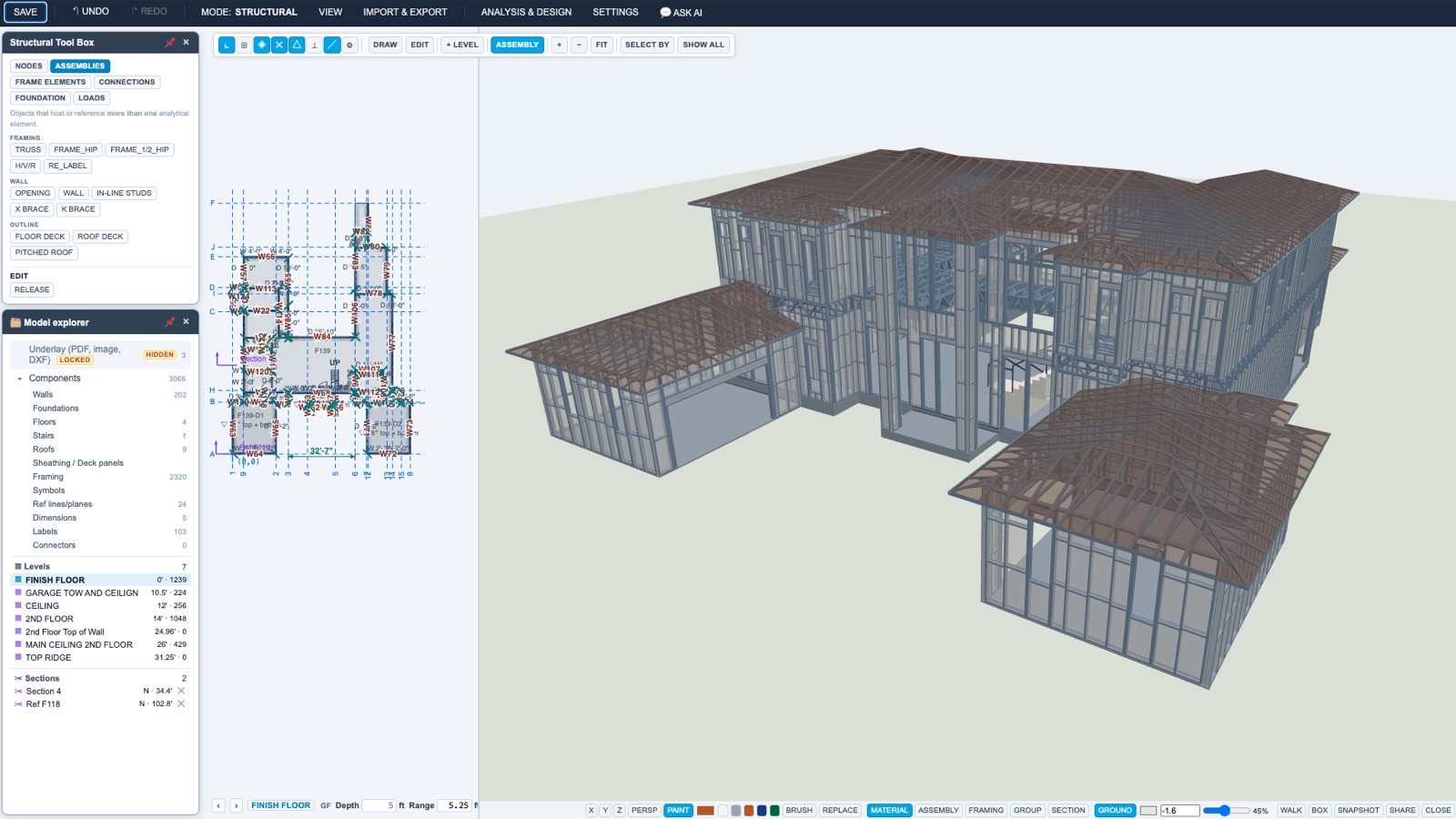
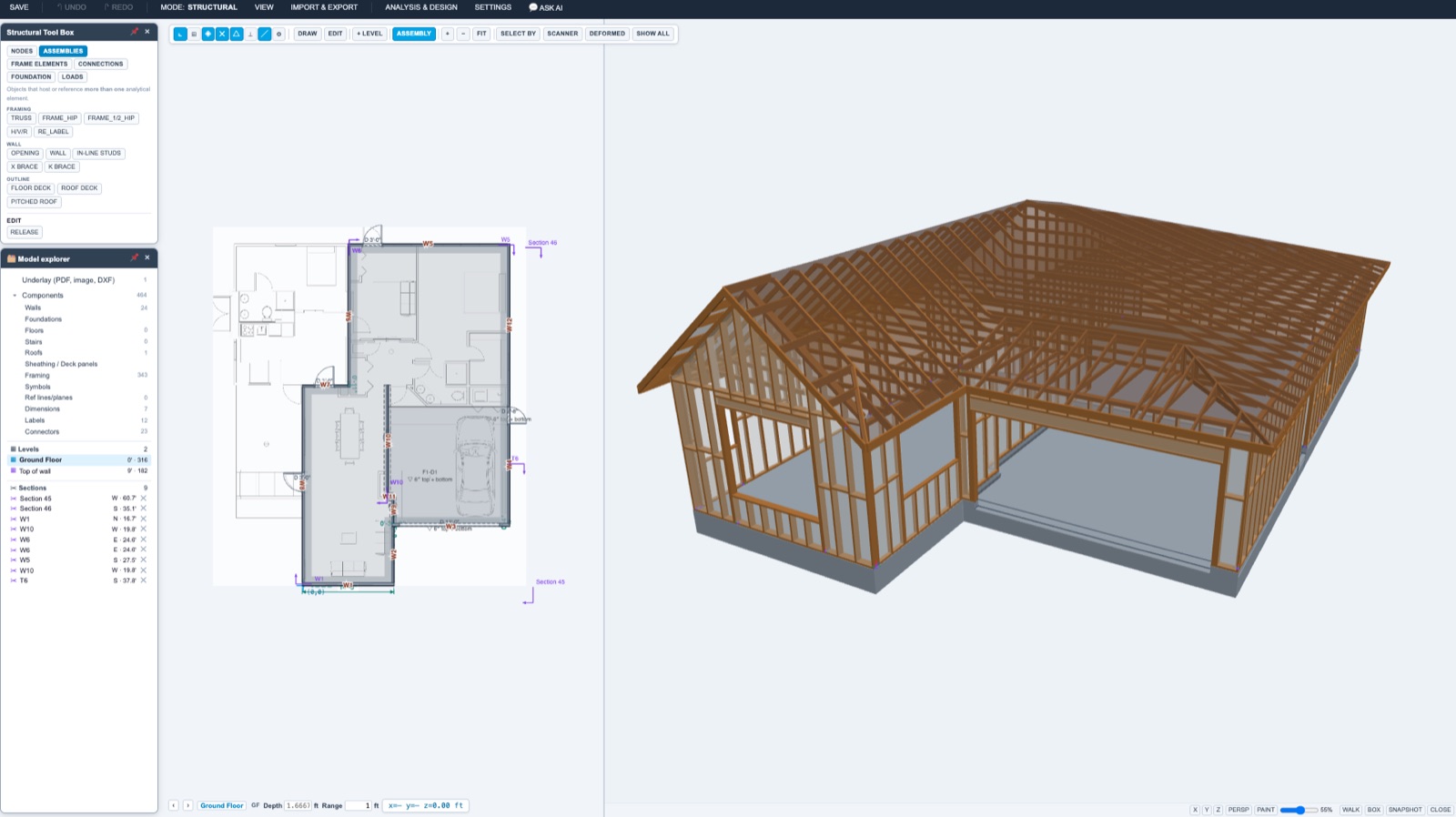
The structural model comes from the architectural one
In traditional structural software the model is built from scratch. The building is redrawn as nodes and lines, and its geometry is simplified until the solver can read it. Nothing in that software frames a wall, an opening, a roof or a floor, so the framing is drawn somewhere else again.
In PerCode AEC the structural model is derived from the architectural model. 3-D elements that touch are connected, and those connections are the load path. Walls, roofs and floors are framed from what you drew. The wind, seismic, snow and gravity loads are applied from the model and the site, once you have answered the questions the code leaves to the engineer.
Around the model: schedules, an extensive product catalog you can add to, PDF and DXF underlays in, and DXF, PDF, IFC and shareable 3-D links out — and the complete design report, ready to stamp.
One model, two modes, two views
Most building jobs are drawn in one program, calculated in another, and checked with a spreadsheet, and the three drift apart with every revision. PerCode AEC keeps one model. The drawing is the model, and the analysis is read from it at the moment you run it, so there is no second model to keep in step by hand.
Architectural mode is where a model starts: walls, doors and windows, roofs, decks, slabs and depressions, drawn over a PDF or DXF underlay with levels and reference lines taken from the drawing. Structural mode adds the framing, the supports, the loads and the design run. Every element sits on a level with an offset, so a wall, a roof or a slab is placed the way the drawings dimension it.
Every structural element has a physical view — the member as it will be built, with its real size and position — and an analytical view, the wire model the solver reads. Both are cuts through the same 3-D model, so they cannot disagree.
What it models
- Walls framed stud by stud — studs, king and jamb studs, cripples, sills, headers and top and bottom plates — with the openings you drew, sheathing, and joins between walls that touch.
- Roofs generated from the plan outline: hips, valleys and gables, including a roof that is hipped at one end and gabled at the other.
- Trusses laid out along the roof, either as lines that carry load to their bearings or as trusses with real member sections that are designed.
- Floor and roof decks, beams, columns, posts, in-line studs and multi-ply members.
- Foundations — wall footings, spread footings, mono slabs and stem-wall foundations, slab depressions.
- Connections — Simpson Strong-Tie hold-downs, straps and ties from the current catalog, and bolt, nail and screw groups.
- A product catalog you can extend — connectors, sheathing and deck panels, steel, cold-formed and engineered-wood sections. Add a product in the Catalog Manager, and each project keeps a short list of the products it uses.
- Releases and links where a joint does not carry moment or two parts of the model meet.
What it designs, and to which clauses
A design run analyses the whole building once and checks every element from that one analysis. Each check in the report names its standard and clause. The material decides the standard:
| Material | Standard | What is checked |
|---|---|---|
| Wood | AWC NDS 2024 (ASD) | Bending with beam stability (§3.3), shear (§3.4), compression with column stability (§3.7), tension (§3.8), combined and biaxial loading (§3.9, §15.4) |
| Cold-formed steel | AISI S100-24 | Compression (§E2–E3), tension (§C2.1), flexure (§F2–F3), shear (§G2.1), combined loading (§H1.1, §H1.2). Webs are checked as punched. ASD or LRFD |
| Hot-rolled steel | AISC 360-22 | Compression (§E3), tension (§D2), flexure (§F2–F5), shear (§G2.1), combined loading (§H1.1) |
| Reinforced concrete | ACI 318-19 | Flexure (§22.3), axial with slenderness (§22.4, §6.6.4), one-way shear (§22.5); spread and wall footings |
| Masonry (CMU) | TMS 402-22 | Axial with slenderness, flexure, shear and combined loading (§8.2, §9.3) |
| Wood shear walls | AWC SDPWS 2021 | Segmented and perforated methods (§4.3), aspect-ratio limits, unit shear from Table 4.3A; or a product's evaluation-report values |
| Wood diaphragms | AWC SDPWS 2021 | Blocked and unblocked diaphragms from Tables 4.2A and 4.2C, chosen from the fastening schedule |
| Floor and roof panels | APA PDS | Out-of-plane bending, shear and deflection under gravity loads |
| Connectors | Manufacturer catalog · NDS · AISI | Catalog capacities with the catalog's interaction; bolt and screw groups from NDS and AISI |
Wall studs, headers and plates are designed as members, not looked up: a header that fails moves up its size list until it passes, and the report says which size it settled on and why.
Loads you can follow
The load wizard reads the building from the model and the site from the project, asks the engineer the questions the code leaves to judgement, and writes each hazard as a full calculation — the same report the stand-alone load modules produce — to ASCE 7-16 or ASCE 7-22.
The site hazards — wind speed, snow and seismic values, and flood zone — are read for the project address from the ASCE Hazard Tool and FEMA's flood maps, and stay with the project.
- Wind — main wind-force resisting system pressures on walls and roofs, and components and cladding on the roof zones, with effective areas per §26.2.
- Snow — ground, flat-roof and sloped-roof snow with the site's climate zone.
- Seismic — the seismic response coefficient from Chapter 12, distributed per §12.8.3 from the model's own mass, as ±X and ±Y patterns or eight under the §12.5 orthogonal combination. A structure exempt under §11.7 gets no seismic patterns at all.
- Gravity — live loads from the occupancy short list of Table 4.3-1, and dead loads from the assemblies you build.
- Combinations per ASCE 7 §2.3 (LRFD) and §2.4 (ASD), each material read on its own basis.
If the building or the site changes after a hazard was calculated, the design run refuses until the calculation is brought up to date, and one button recalculates it with the answers you gave the first time.
The analysis
A three-dimensional frame solved by the direct stiffness method, six degrees of freedom per node, linear and static. Members are meshed where they meet, releases are honoured, and a model that cannot carry its load stops the run instead of returning numbers.
Serviceability is checked from the same solution: member deflection against IBC Table 1604.3 or IRC Table R301.7, wind drift against your limit, and seismic drift amplified by C_d/I_e (§12.8.6) against Table 12.12-1.
What you hand in
- A PDF report with the sections you choose: loads, the analysis, every element's checks with their clauses, key plans and load tags.
- Drawings exported to DXF and PDF, from the canvas or as sheets.
- Schedules of connectors, wall openings (rough openings, kings, jacks, headers and sills) and posts.
- A 3-D link to the view on your screen, for anyone with a browser (paid plans; each link lasts seven days).
- An IFC4 file of the model for the architect's or contractor's BIM tool.
- Project files that keep their history: every save keeps a version, and the project manager knows which reports are out of date.
Code basis
Every account practises in one state, chosen at signup, and that state's adopted codes set the basis in every module — Florida runs the FBC 2023 today and the FBC 2026 ahead of its December 31, 2026 effective date. A national model-code basis (IBC with ASCE 7, no state) is open to every account.
How it compares
PerCode AEC does work that is usually split between a BIM program, a framing add-on, an analysis program and a calculation package. This table sets it beside the tools engineers and designers use for homes and mid-size buildings.
| Feature | PerCode AEC | Revit | ETABS | SAP2000 | ENERCALC | Calcs.com | iStruct | StrucSoft | Vertex BD | WoodWorks |
|---|---|---|---|---|---|---|---|---|---|---|
| Builds the architectural model | Yes | Yes | No | No | No | No | Partial | In Revit | Yes | No |
| Structural model taken from the architectural model | Yes | Yes | Linked from Revit | Linked from Revit or IFC | No | No | Not stated | No | No | No |
| Frames walls, roofs and floors | Yes | Add-on | No | No | No | No | Partial | Yes | Yes | No |
| 3-D frame analysis | Yes | Add-on | Yes | Yes | Yes (ENERCALC 3D) | Not stated | Not stated | No | No | Not stated |
| Member design to US codes | Yes | No | Yes | Yes | Yes | Yes | Not stated | Via plug-ins | No | Yes |
| Light-frame shear walls and diaphragms | Yes | No | Not stated | No | Shear walls | Yes | Not stated | No | No | Shear walls |
| Wind, seismic and snow loads to ASCE 7 | From the model | Not stated | Wind, seismic | Wind, seismic | Per module | Per calculator | Not stated | No | No | Wind, seismic |
| Site hazards from an address | Yes | Not stated | Not stated | Not stated | Not stated | Yes | Not stated | No | No | Not stated |
| Design calculation report | Yes | Not stated | Yes | Yes | Yes | Yes | Not stated | No | No | Yes |
| Schedules | Yes | Yes | Not stated | Not stated | No | Not stated | Material lists | Yes | Yes | No |
| Imports DXF/DWG or PDF | Yes | Yes | DXF/DWG | DXF/DWG | Not stated | Not stated | Not stated | In Revit | Yes | Not stated |
| Exports IFC | Yes | Yes | Yes | Yes | Not stated | Not stated | Not stated | In Revit | Yes | Not stated |
| Runs on | Windows and macOS | Windows | Desktop | Desktop | Windows and cloud | Web browser | Not stated | Revit add-in | Windows | Not stated |
Read from each vendor's own pages on October 20, 2026. "Not stated" means the pages we read do not say — the product may still do it. If a cell is wrong, write to us and we will correct it. hello@percode.ai
Revit is Autodesk Revit; ETABS and SAP2000 are from Computers and Structures, Inc.; iStruct is from Simpson Strong-Tie; StrucSoft is StrucSoft Solutions' framing software for Revit; WoodWorks is the AWC and Canadian Wood Council design software. Product names are trademarks of their owners.
Sources
- Revit: https://help.autodesk.com/cloudhelp/2025/ENU/Revit-DocumentPresent/files/GUID-A5E61A08-9635-44D0-93CA-75C15282119B.htm
- ETABS: https://www.csiamerica.com/products/etabs/features
- SAP2000: https://www.csiamerica.com/products/sap2000/features
- ENERCALC: https://enercalc.com/product-specifications/
- Calcs.com: https://calcs.com/
- iStruct: https://www.strongtie.com/digital-solutions/software/istruct
- StrucSoft: https://strucsoftsolutions.com/
- Vertex BD: https://vertexcad.com/bd/products/
- WoodWorks: https://awc.org/resources/woodworks-software-for-wood-design/
What it will not do
An engineer should know the edges of a tool before relying on it. These are PerCode AEC's:
- It does not run second-order (P-delta) analysis or include shear deformation; the analysis is linear and static.
- It does not check member bearing (NDS §3.10) or cold-formed steel web crippling.
- It does not design truss plates, or trusses drawn as load lines; those are for the truss manufacturer's engineer.
- It does not design basements or the slab on grade itself; it designs the footings and thickened edges under it.
- Wood is designed by ASD only.
- Floor and roof panels are checked for gravity loads only.
- The IFC export places the whole model on one storey.
- It does not design one truss at a time; it designs the building.
- It does not stamp anything. The engineer of record reviews and signs; the software never does.
Which plan includes it
Architectural mode
Walls, openings, roofs and slabs — the building, drawn over your plans. Included in Basic, Structural.
Structural mode
Frame it, solve it, and design every member against the code. Included in Structural.
The free trial opens every mode. See pricing
Draw it once. Design all of it.
Start the free trial, then download PerCode AEC and open your next job in it.
Start free trial